Rhino Clipping Plane Section Drawing
Generating Plans and Sections
In this practice you will be using your Rhino file to generate building plans and sections. Once you have generated the two-dimensional drawings, y'all will export the drawings equally Illustrator files.
PS.1. Make a copy of your projection file.
PS.2.Name your file with your name followed past Plan. For instance, JohnSmith_Plan.
PS.three. The first few steps involve preparing your model for the procedure of making the plans and sections. Remove whatever cameras and artificial lights from your model. Select and erase/delete them. This is not necessary for generating the views, but it will brand it easier for you lot to piece of work.
PS.4.Reset the Perspective view to the default view.

PS.five.Ungroup any groups that y'all have in your model. To ungroup them, type Ungroup at the command line, and select the grouped item(s). You can brand a window around all of the objects to more quickly select them.
PS.half dozen.Turn off the Context layer. Create a new layer chosen Basis. The layer color and material are non of import. Brand that new layer the electric current layer.
PS.7. Showtime your property line 5 feet toward the outside. Delete the original property line.

PS.8.Extrude the plane using the ExtrudeCrv control. Extrude the aeroplane -v' (negative v feet). The top of the plane should be at 0'-0" on the Z-axis. Cap the extrusion.

PS.nine.Plow off any additional layers that will not appear in the drawing. This includes layers from previous studies, context, streets, and property lines. Note: You can also erase objects on those layers. If you choose to exercise this, plow off the layers or lock the layers with objects you would like to keep. Erase everything else. Eliminating unnecessary objects volition get in easier to piece of work.
PS.10.Layers need to exist on and unlocked and grouped elements need to be ungrouped to be part of the 2D model. Unlock all layers that will appear in the program and section drawings. Ungroup the elements of your building. Information technology is important that you do not explode elements to the level of surfaces.
PS.11.You will be making one plan cut through your projection. In preparation for making the plan cut you will need to create a horizontal plane where you lot intend to cut your program. This airplane will be the location of your plan cut. It will be raised above the ground plane.
PS.12.Create a plane past tracing the corners of the ground airplane. The plane tin be drawn on any layer.


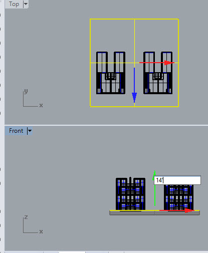
PS.13. Since the top of your ground plane is 0'-0" on the Z-axis, the airplane you just made needs to exist moved up. Typically a plan is cut about 4'-0" to a higher place the flooring. I recommend a height of 14'-0" above the ground plane. This would identify the plan cut at 4'-0" above the second flooring. Please note that your project may exist different, and may require a different superlative. If you exercise use a dissimilar superlative, enter a specific distance and brand certain to remember the altitude because you will demand information technology later. To motility the plane, select the surface.

PS.14.In the Front view click on green pointer and input the height. Plough the Gumball on if y'all don't see the green, blue and blood-red arrows.

PS.xv.The image below shows the new location of the plane from the Perspective view.

PS.16. Create a new layer called PlanCut, and make that new layer the current layer.
PS.17. The cut profiles will be generated at the height of the plane. Input the command IntersectTwoSets. Choose the aeroplane and press Enter.

PS.18. You will be prompted to select the second set up of objects. In the Peak view select the edifice components and press Enter.

PS.19.In the Perspective view y'all can run into the new lines that have been generated.

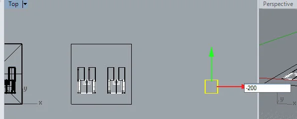
PS.19.While the pick is still highlighted use the Summit view Gumball to move the lines over 200 feet. If those elements are no longer highlighted, y'all tin turn off all layers except the PlanCut layer and re-select the lines. The reason for moving them over 200 feet is to see them and work with them more easily.


PS.xx. From the Forepart view move the lines down to the level of the footing plane which is at 0'-0" on the z-axis. Your 2d drawing should drop down to the same level as the ground plane.


PS.21.The last few steps described how to create lines from the masses that the plane cut through. Adjacent you will exist showing the elements that are below the cut aeroplane. To do this you will need to create a clipping airplane at the same tiptop as the plane used for the IntersectTwoSets control.
PS.22.Type in ClippingPlane at the command line. Click on the corners of the plane you used to generate the plan cut lines.

PS.23.Select the clipping aeroplane. The clipping airplane has diagonal lines from corner to corner. In the Properties window select the Clipping Plane icon and turn on the plane in the perspective and the height view past placing a check in the box side by side to Perspective.

PS.24.Delete the original plane then that you can meet the lines that will be generated in the next step. For example, the lines of the stair should announced.

PS.24.While you are in the meridian view type Make2D at the command line. Select the entire 3D model. All 3D objects beneath the clipping plane must exist selected. It is all-time to select from correct (1) to left (2). This is known as a crossing, and information technology will include all objects inside or touched by your crossing window. If yous select (2) and then (ane), simply objects inside your window will be selected.

PS.25. Make sure than yous are in the Tiptop view earlier you press Enter. Press Enter.

PS.26.Alter the setting equally shown beneath. By placing the cartoon on the current CPlane it will be located on pinnacle of the model in Summit view.

PS.27.While the objects are highlighted motion them 200 anxiety to the correct. They should be straight to a higher place your plan cutting lines.

PS.28. Verify that the plans from the Make2D and IntersectTwoSets operations are on elevation of 1 another.

PS.29. In an architectural plan drawing, the convention is to show the edges of planes above with a subconscious or dashed line, but the default direction of the clipping plane is downward, and and then those objects above exercise not appear. To testify the objects in a higher place, you must flip the direction of the clipping plane. To do this select the clipping plane and in the Properties window click on the Flip Direction button. After you use the Make2D command, the 2d cartoon will appear on the ground plane beneath the building. Uncheck the Front end box and so that it is visible in the Front view.

PS.30. In the perspective view, the portion to a higher place the clipping plane is now visible, just all objects beneath the clipping plane are non. Keep in mind that the 2D drawing elements are not visible because they at a height of 0'-0" on the z-centrality. To make them visible once more, you lot tin can flip the clipping aeroplane again or delete the clipping airplane altogether.

PS.31. A aeroplane has been shown at the top of the building to illustrate an overhead plane status and the process for this operation.

PS.32. Use the Make2D command as you have previously and select items that have the overhead plane condition. You can select the whole model, only it will create a number of redundant lines that may need to be erased layer. Notice how the programme drawings practise not announced. This is because the clipping plane is looking upwardly. If you know which items appear above, simply do not appear beneath, you can select but those items as shown beneath.

PS.33. Make sure that the Top view is the electric current view. When yous press Enter, it will appear that no cartoon was produced in the Summit and Perspective views. Considering yous unchecked the Forepart box in the Clipping Plane window, the new drawing should announced in the Front view. This time move your drawing 400 feet to the side. This will enable you to piece of work with the layers before placing on top of the other programme elements.

PS.34. To meet the second plan drawings, flip the clipping airplane back to its original direction.

PS.35. Create a new layer called Plan-In a higher place. Put your new linework on that layer. In illustrator you will be changing its linetype to subconscious or dashed.

PS.36. Move the linework 200 anxiety to the left so information technology rests on summit of the other plan drawings.

PS.37. Erase the square that represents the edge of the Basis plane.

PS.38.Adjacent you will exist exporting the second drawing to Illustrator. Type Export at the command line. Select the plan drawings.

PS.39.Save the file equally shown beneath.

PS.40.Alter the scale for to 1/viii" = one'-0" as shown below.

PS. 41. Note: if y'all open the file in Illustrator, don't be alarmed if you don't see the drawing. Merely keep pressing Ctrl + - to zoom out. You volition observe the drawing outside of the sheet.

PS.42.Salvage and exit the Rhino file.
PS.43. Brand a copy of the file and rename information technology with your name followed by Section.
PS.44.Open up the new file.
PS.45. Erase the 2D plan drawing, the clipping plane and the horizontal plane.

PS.45. Y'all will be repeating the steps above to generate a section through your model. Cull a location that is interesting spatially. The department illustrated beneath will cut through the stairs and will look toward the east.

PS.46. Go to the view that looks in the direction of your section and brand a plane that is includes your entire building and the ground plane. For the section shown above, information technology would be the Left view. You may need to modify the view depending on your choice for the placement your section.

PS.46.Brainstorm by making a plane in that view. The plane should include the whole building and the ground aeroplane.


PS.47.Go to the Top view and Zoom to the extents of your model. The airplane will appear off to the side. Use the arrows of the Gumball to position the plane.


PS.48. Create a new layer called Section Cutting and make that layer the electric current 1.
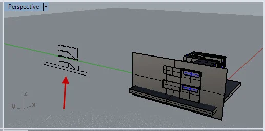
PS.49.Apply the IntersectTwoSets control to create the section cut lines. Cull the plane first, Press Enter. Then choose the unabridged model. Exist sure to include the footing mass. In the image below, the lines of the section have been created. While the lines are still highlighted, movement the section lines to the side using the Gumball. In the paradigm below the lines are being moved 200 anxiety to the left in the Left view. Depending on the location of your section you may need to use a unlike view for this process.

PS.fifty.The image is visible to the left in the image beneath.
PS.51.Make a new clipping plane from the same view that you drew your airplane for the previous steps. Trace the airplane in that view. The clipping airplane is volition be square and will extend beyond the airplane that you trace.

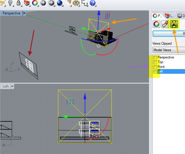
PS.52.Click on the clipping plane and brand sure that the box is checked for the view. in the epitome below the box side by side to Left has been called because that is the view associated with the department.

PS.53.In your section view use the Make2D command to generate a 2-dimensional drawing of the objects across. Select all of the 3D objects and printing Enter. When the 2d Options window appears, make sure that the Current CPlane button is selected and that the Hidden Lines appear.

PS.54.The second drawing may not be visible in all of your views. Why? Because the Clipping Plane has been applied to some of the views.

PS.55.To make the drawing visible, select the clipping plane and uncheck the boxes next to the view. The cartoon volition announced, but it volition non exist on the aeroplane of your clipping plane.
PS.56. Select the 2D drawing elements while you lot are in the Perspective view. Movement them while you are in your section view.

PS.57.Delete the box representing the plane well-nigh your projection.
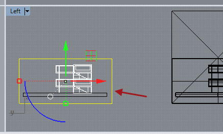
PS.58.The IntersectTwoSets drawing (orangish arrow) needs to exist moved and then that it is on acme of the Make2D department drawing (red arrow).

PS.59. Find a common point on each drawing and make a circle at those points. In the paradigm below a dark-green circle has been drawing on the IntersectTwoSets drawing and a yellow circle has been drawn on the Make2D drawing. With the Center object snap turned on, you tin movement the IntersectTwoSets drawing so it rests on elevation of the Make2D drawing.

PS.60.ClickOnce you lot have aligned the two drawings, erase the reference circles, and Consign the section equally an Illustrator file. Name the file with your proper name followed by Section.
PS.61.Upload the two Rhino files and the ii Illustrator files.
.
.
.
thompsonthersim1982.blogspot.com
Source: http://www.cccarchitecture.org/generating-plans-and-sections
0 Response to "Rhino Clipping Plane Section Drawing"
Postar um comentário